What's new

OM617 Motor Mounts for a 404

Austin

Blame Canada
1
1
1
Joined
May 1, 2020
Member Number
1
Messages
3,119
Loc
St.Louis, MO
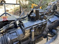
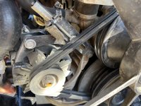
Unimog 404’s have a single motor mount in the front attached to a pendulum on the frame. This allows the drivetrain to move since the frame is designed to twist.
IMG_9155.jpeg


The brackets don’t work with the motor I’m swapping in, it had 2 traditional side motor mounts. So I need something new…. And space saving

I’d really like to see something with dom like this:
IMG_9153.jpeg


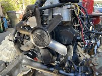
  • The motor is about 600LBS
  • The actual motor mount goes where that clean plate is on the right side of the tube
  • That pendulum would hang down (didn’t want to cut hose)
  • This hose has a rolled look now but it’s just for illustration. It would be more of a J
  • The tube would be about 22" long
  • That 3/8 bracket at the top would be the weld point it would bolt to the factory motor mount position.
I've seen tons of DOM used to make motor mounts ... I think my real question is what kind of weight do you trust a piece of 22" dom to support with a point load somewhere in the bend?

My only other option is to fab up something like this:
IMG_9156.jpeg

There would be more bracing between the sides and tabs to mount it…. But I like tube route a bit more if it would hold it
 
Last edited:
Something like that holds up each corner of my leaf springs rigs without a problem.
 
I think I was 1/2 asleep when I posted that. Added more info I left off the first post.

Also should of added that the tip would have to be notched to allow the pendulum movement. Something like this:
IMG_9157.jpeg

Not sure how to spec a DOM size capable of standing up to that kind of notch.

Something like that holds up each corner of my leaf springs rigs without a problem.
How long are they?
 
What size is the OD of that bushing that the shackles connect to. The floating bushing you want to tie into?
 
Why can't you do both? Do the tube and then add brackets that tie into the ears that the second design would have used.

It's a tension/compression design. Needs less strength than something in shear or torsion.
It's also overhung by 4" or so and has the entire torque of his drive-train on it.
 
What size is the OD of that bushing that the shackles connect to. The floating bushing you want to tie into?
40mm or about 1.5"


An alternative to notching the tube would be full circle tabs.

20231025_074516.jpg
Thats a good idea I hadn't thought of, I started going down another path but now you got me thinking again. If I had somebody with a tube roller near by I'd be on it.

Why can't you do both? Do the tube and then add brackets that tie into the ears that the second design would have used.


It's also overhung by 4" or so and has the entire torque of his drive-train on it.
Yea I didn't set up the question well. This mount is a single mount on the front of the motor, there is a point at the back of the case/tranny combo that is the only other mounting point. Its this point the drivetrain pivots on.


The length of the tube, and not knowing anybody to roll that bend, I started down another path using a piece of the factory mount and will add some additional bracing.
IMG_9163.jpeg


IMG_9164.jpeg


IMG_9165.jpeg


I’ll be building the green drawing & cardboard from .25” plate. That’ll give me a mount for the block then I can just bolt the factory parts to the front of that. I think it addresses the important loads
 
Last edited:
That looks like a much better way to go about it.

Is that stock piece that bolts to the block cast iron?
 
Is that stock piece that bolts to the block cast iron?
It is. I don't have experience welding cast iron to plate steel which is why I''ll be bolting it to the plate vs trying too weld to it and make it all once piece.
 
Trying to keep it ‘original’ as possible?

I’m not familiar on unimogs. What other mounts it’ll have?
Not going for original, I'd already be failing miserably in the eyes of the restorer types lol. Until this rig I never seen a mount like this, trying to keep it since it's a good design (for its original motor) and incorporates two bushings.


The whole drivetrain mounts to one rotating crossmember you can see in the middle of this pic:

As the frame twists, the crossmember twists and can swing the front of the motor to the left or right a bit, thats why there is this pendulum support for the front of the motor.
 
Until this rig I never seen a mount like this, trying to keep it since it's a good design (for its original motor) and incorporates two bushings.
Thanks! That clear up a lot.

Do you have free space on left and right side of engine block to frame rails? under the oil pan? Essentially move the pendulum motor mount straight back, and build a crossmember wrapping under the oil pan to mount it to? (crossmember bushed at frame rails to allow frame twisting as originally designed)

Or make two pendulum mounts on both side of the block to be mounted to respective frame rails? One side a hanger and other is to be inverted, to not fight each others when frame rails are twisted.

Is this going to be wheeled hard? Look like the trans or its long bell housing will break in half when bouncing or hard landing. A long span!

The more I think, the more I become uncertain on what can be done and not mess up on how engine/drivetrain weight will be distributed on frame and/or clearances needed around the engine as frame and cab twist around it :homer:
 
what kinda of budget you working with?

how common is your motor swap in the that world?
 
That top bracket that bolts to the block. It only uses two bolts with the stock engine?

Do you still have this picture without all the green on it?
img_9164-jpeg.763289


I think your headed down the right path.
 
what kinda of budget you working with?

how common is your motor swap in the that world?
Motor mount budget? My budget is whatever is the best solution ... I don't have stupid money though.

It's a lot of fab work so it's not done by a lot of people... but if you're up for it, this is typically the motor. So there are examples out there. What makes this diffrent from most is that they don't have the serpentine conversion, upgraded injection pump, hydro steering pump and potentially a PTO driveshaft to sit right next to this mount.... all of which it kinda bling :smokin:


Thanks! That clear up a lot.

Do you have free space on left and right side of engine block to frame rails? under the oil pan? Essentially move the pendulum motor mount straight back, and build a crossmember wrapping under the oil pan to mount it to? (crossmember bushed at frame rails to allow frame twisting as originally designed)

Or make two pendulum mounts on both side of the block to be mounted to respective frame rails? One side a hanger and other is to be inverted, to not fight each others when frame rails are twisted.

Is this going to be wheeled hard? Look like the trans or its long bell housing will break in half when bouncing or hard landing. A long span!

The more I think, the more I become uncertain on what can be done and not mess up on how engine/drivetrain weight will be distributed on frame and/or clearances needed around the engine as frame and cab twist around it :homer:
Lots of things have been tried in the past. My original idea was a 1.75 DOM loop that went from motor mount, under the oil pan and up to the other motor mount. Then make a pendulum on the bottom. That would require welding to the frame and ... thats a big Nono in the mog world. Supposedly is some kind of spring steel that allows it to twist and flex. I honestly have not had it long enough to know .... all I do know with all my research is ... don't modify the frame so it can still twist. I debate how much weight does it really take in the bed to get it to twist .. but I don't know enough to start taking chances.

That top bracket that bolts to the block. It only uses two bolts with the stock engine?

Do you still have this picture without all the green on it?

I think your headed down the right path.
The factory bracket was a bit of a C that looped behind/under the crankshaft balancer and had two similar bolts on the other side. No room for that on this motor. You can kind of see the other side here:
IMG_9155.jpeg


No green….
IMG_9164.jpeg
 
Moved the thread and changed the title to more accurately describe the direction the topic went
 
The factory bracket was a bit of a C that looped behind/under the crankshaft balancer and had two similar bolts on the other side. No room for that on this motor. You can kind of see the other side here:
IMG_9155.jpeg


No green….
IMG_9164.jpeg

Was kind of afraid of that. It seemed odd that a 600lb engine would be held by a couple bolts.

I still think you're on the right path with all the green and card board "brackets". The more bolt holes in the block you can grab the better.
 
Maybe add a plate to double shear from behind that bolt that you already have installed through the block.
That'd give you a nice big plate that could be shaped to brace both the cardboard piece and green squiggly piece.
Looks as though it could also extend up a bit and be tagged to pick up the bolt hole to the left of the dipstick?
 
Maybe add a plate to double shear from behind that bolt that you already have installed through the block.
That’s a good idea. I need to build a mount for the Hydro pump off the side of this bracket, and I may try to tie into that same bolt.

Happy with the way this turned out, not only is it bolted in for spots to the block, but the tabs for the bolts are also sitting on the plate.
IMG_9211.jpeg

IMG_9212.jpeg


I used .75 plate & .25 for the gussets for the new mounting points off the crossmember. Still need to drill and tap that for bolts. I screwed up and only ordered one new bushing, the top one should be here any day, and I can finish assembly.
 
Last edited:
Just to follow up and close out this thread, I needed to mount a RadialDynamics PS pump and the ideal placement would be to piggyback on the motor mount. Should have thought of that the first go around.

Since making this I got a 3D scanner and Plasma Table so I scanned part of the block…..
Screenshot 2024-01-20 at 10.17.45 PM.png


Then took that scan into Fusion360 and connected the bolt holes with .25 plate, also took Wendle advice and made that top bolt double sheer…
Screenshot 2024-01-20 at 10.18.52 PM.png


Then sent that to the plasma table to be cut. Here is the finished mount:
IMG_9691.jpeg

IMG_9701.jpeg
 
Last edited:
Just to follow up and close out this thread, I needed to mount a HYDRODYNAMIC PS pump and the ideal placement would be to piggyback on the motor mount. Should have thought of that the first go around.

Since making this I got a 3D scanner and Plasma Table so I scanned part of the block…..
Screenshot 2024-01-20 at 10.17.45 PM.png


Then took that scan into Fusion360 and connected the bolt holes with .25 plate…
Screenshot 2024-01-20 at 10.18.52 PM.png


Then sent that to the plasma table to be cut. Here is the finished mount:
IMG_9691.jpeg

IMG_9701.jpeg
Tagged me but it wasn’t me, looks good though.
Make sure to belt pulleys are aligned and flush.
 
That's a very cool little assembly now.

Pure seat of the pants judgement is that the window cutouts look a little big and strength stealing in some of the parts, but I've no maths to back that up :clown:
 
Out of all the different engine choices why did you chose that one?
 
Out of all the different engine choices why did you chose that one?
  1. I wanted to keep a MB motor in a MB vehicle.
  2. OM617s directly bolt to the Mog's bell housing.
  3. Space is very limited, OM617s have been done before and shown to fit.
  4. They are about 2.5x the HP over the stock M180.
Now Hindsight .... I wish I would have got a OM606, which most say is physically too big to fit.... and they are in stock form. After the firewall customizations I made and stumbling across OM606 custom manifolds that are out there I believe I could have easily fit a 606 in the same space. They are much simpler to keep running and can handle 500HP without any modifications to the internals.

Since I got time/money into this 617 I'm going to run it until the rig is wheeling, then start a 606 build to swap in one winter. I've already got my eye on one locally.
 
Last edited:
I just saw your post. I converted my 404 3 years ago. Have the cab off right now do some maintenance. Took some pictures today. About to put the cab back on. Did some pretty serious four wheeling last summer and had no issues with the mount. Happy to share any info you need. Where are you located?
IMG_5711.jpeg
 

Attachments

  • IMG_5707.jpeg
    IMG_5707.jpeg
    4.1 MB · Views: 1
  • IMG_5709.jpeg
    IMG_5709.jpeg
    3.3 MB · Views: 1
  • IMG_5710.jpeg
    IMG_5710.jpeg
    3.8 MB · Views: 1
Last edited:
Top Back Refresh